What made me 3D print a bike part?
Years ago, I answered an advert in the club forum from someone wanting to give away a Pro Vibe 27.2 mm seatpost. I was riding a beautiful lugged steel road bike made from Reynolds 653 Double Butted tubing at the time. This was a ‘perfect match’, a dream come true. So, I replied and went to fetch it.
Here I am again… Yet another bike part I can’t source anywhere.
Most things that are too good to be true are… and although I returned home with a lovely, feather-light carbon seat post in pristine condition with a Di2 battery mount inside, there was no saddle clamp to go with it. Bum. It was useless if I couldn’t mount a seat on the thing… So, I went online to find the missing parts…
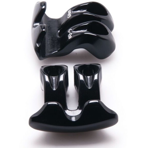
Here I am again… Yet another bike part I can’t source anywhere. The aluminium clamp I need is not available—well, not all of it. The clamp comes in three parts. One base part and two curvy “wings” that snake over the saddle rails and tighten down under the knuckle or head of the seatpost onto the base part using two small bolts. It’s difficult to describe. So take a look at the pictures.
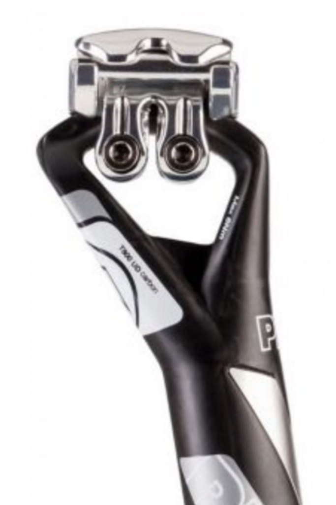
An image of the ‘out of stock’ seatpost with clamp found on a bike shop site provides visual clues.
The “wing” bits were available to buy; there are two different types. One for round metal seat rails and another for oval carbon rails. However, the bit that everything clamps down on was nowhere to be found.
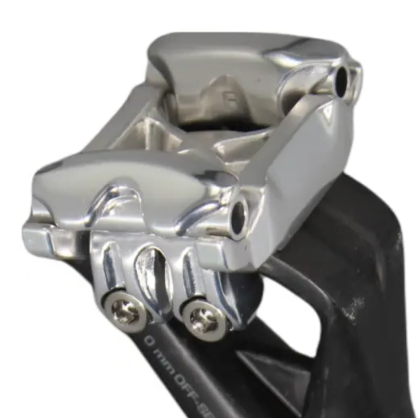
From a different angle you get more detail.
All cyclists have a spares box. A bit like a handbag. A spares box is very particular to it’s owner.
Of course, Shimano (aka Pro Vibe) is happy to sell extra parts to fit different saddle rail standards, but they don’t expect you to misplace the base part of the clamp!! Consequently, despite my best efforts, I was left with a hi-end, incomplete part…
Fast forward a couple of years… or more…
Dust had collected on the seat post as it lay there in the spares box for so long. All cyclists have a spares box. It’s a bit like a handbag. A spares box is very particular to its owner. Nobody else knows what the spares box contains. It seems like a jumble and a bit of a mess, but the cyclist knows just how to rummage in their spares box and pull out something that comes in very handy every now and then.
I like to learn things and take on new challenges.
During every rummage, I would catch a sight or a feel of that seatpost, and it played on my mind. So much so that I often entertained thoughts of machining the missing parts by hand from a slug of aluminium. I even considered smelting and casting them (that’s a process of melting aluminium and pouring it into a mold). The challenge was: I had no idea of the dimensions and had nothing physical to refer to, aside from a few ‘out of stock’ photos on the odd bike shop website, but these provided little to go on.
The missing knowledge and the learning curve
I like to learn things and take on new challenges. As the seatpost aimlessly floated around in my spares box over the years, I’d been casually studying CAD software so I could create engineering drawings of bike parts I intended to make. That gave me just enough skill and knowledge to model and crudely render rudimentary things in 3D, which can then be printed out. The magic of 3D modeling is that you can design things on screen and fit them together to see if they might work without actually making anything! So, I considered modeling the missing part and creating prototypes to see if it was possible…
I struggled with several different 3D software packages and settled on Fusion 360 as something I could grapple with.
Then I had another thought… Perhaps I could 3D scan this thing??
My bright idea faced some hurdles. The post and clamp together are a very complex design. Every part had curvy faces and was shapely or wavy in an organic way. How all the parts worked in combination to clamp the saddle was a bit of a mystery. The shapes I needed to model were beyond rudimentary. I lacked the confidence that I could accurately replicate this in any CAD software with so little experience.
I needed to get the knuckle or ‘business end’ of the seatpost into the software with some accuracy. Then I had a eureka moment… Perhaps I could 3D scan this thing? Apparently, in conjunction with an app called Kiri Engine, I can use my phone to achieve this for free!
My first attempts at scanning the seatpost were comic if not tragic.
Then, with a few basic measurements, like knowing the 27.2 mm post diameter, I could import it into the 3D software and reverse engineer the missing part, guided by the pictures I had seen online.
3D scanning using a mobile phone
My first attempts at scanning the seatpost were comic if not tragic. The 3D images I got were all saggy and unrecognisable. The idea is that you simply move your phone around the subject and take loads of photos from different angles.
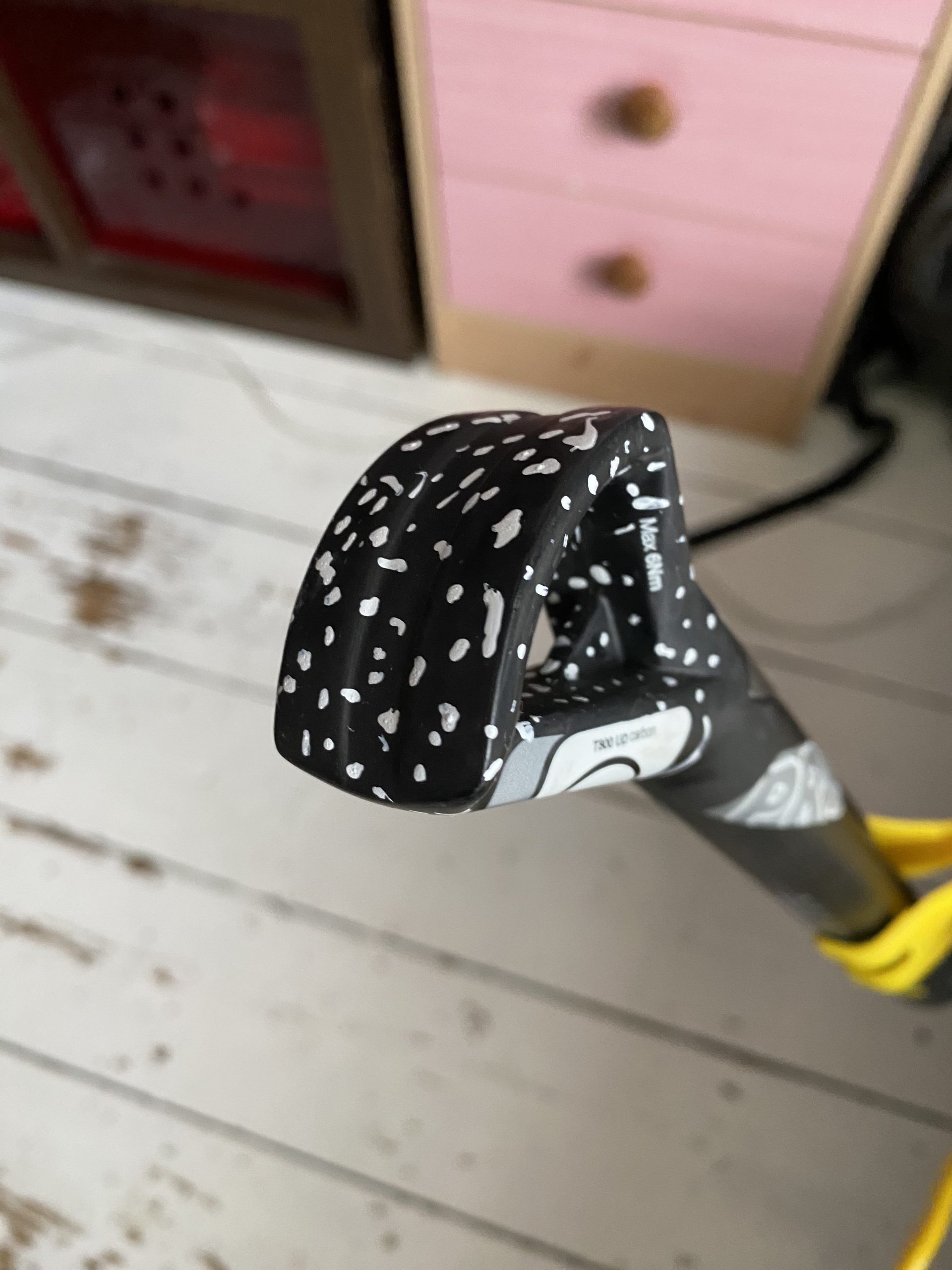
Basically, I was asking the camera on my phone to capture detail from a matt black carbon shape that had no defining features. After a little research, I learned I needed to ‘highlight’ the shape’s surface or give the part some contrast.
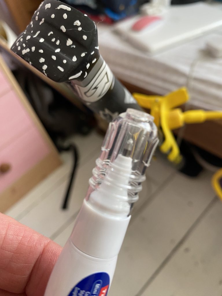
I had to get creative, so came up with the idea of randomly dotting the seatpost with white Tippex (correction fluid). This gave the camera just enough to latch on to.
At the same time, you also need to have significant ‘landmarks’ in the background of the thing you are scanning so that the app is able to stitch all the individual photos together in their correct orientation. Otherwise, you’ll get an image that looks like it’s been eaten by space monsters. So, I made sure the background of the room was busy with stuff.
To my surprise, the resulting scan came out pretty well in the end. The surface of the seat post was a little bobbly, but it ended up being good enough to provide a reasonably accurate model to load into Fusion 360.
Fighting with my lack of 3D modeling knowledge
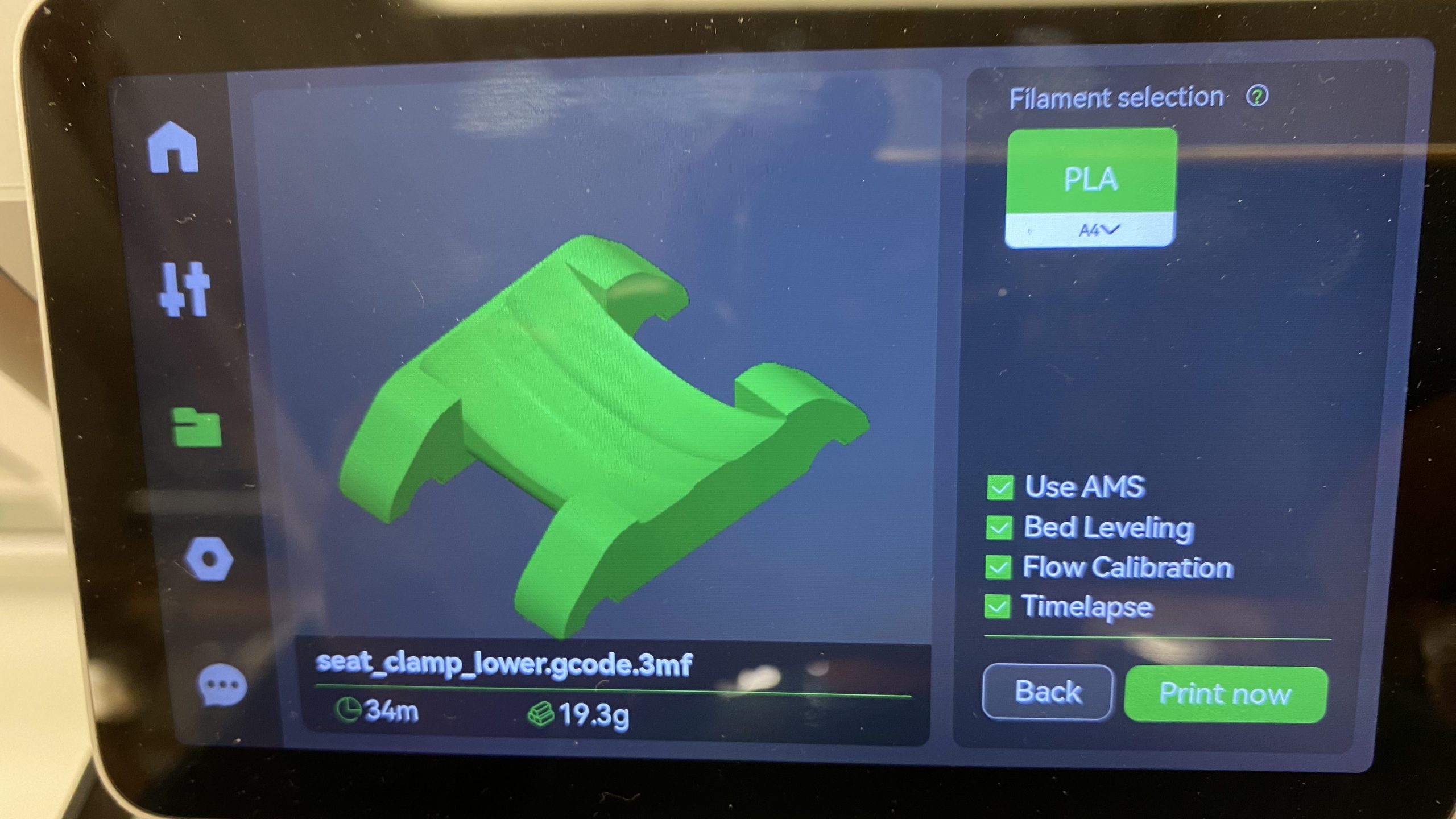
First, I imported the file into the virtual 3D space in the software. I then scaled it to size and oriented it with a 5-degree angle as if it were inserted into a bike frame (the downtube of a bike frame, where the seatpost goes, is usually between a 5- and 7-degree angle). Following that, I simplified the scan and removed everything but the “knuckle.” Afterwards, I did some other 3D magic and shaped something that I thought looked similar to the clamp in the photos. I then floated some imaginary saddle rails over the virtual clamp I had drawn on screen and made sure they fitted snugly into the shape. Eventually, I printed out the result on a 3D printer.
My first 3D print attempts
I had no real idea what I was doing. I had hardly any experience using 3D printers aside from an introduction at the workshop I’m a member of. Amazingly, my first printout resulted in a beautifully formed… NOTHING! Ta-dah! An error on my part saw me start the printer printing without any material, or plastic ‘ink’.
The second attempt was an actual part that resembled my model. Even more amazingly, it fitted! I began feeling slightly encouraged.
Moving on to something more useful
Interestingly, if you can 3D print a part, you are also able to “CNC” or computer control a machine to cut the same part from another material, such as aluminium. I was getting there. The part is small, and I have access to a mini CNC milling machine. I was closing in.
I found a couple of suitable bolts in the good old spares box, and then I had it!
The next step was to order those “wing” parts of the clamp that were available online.
Once they came through, I was then able to take their dimensions and further refine the missing clamp part I had already roughly modeled. I was getting even closer to making something that might actually work.
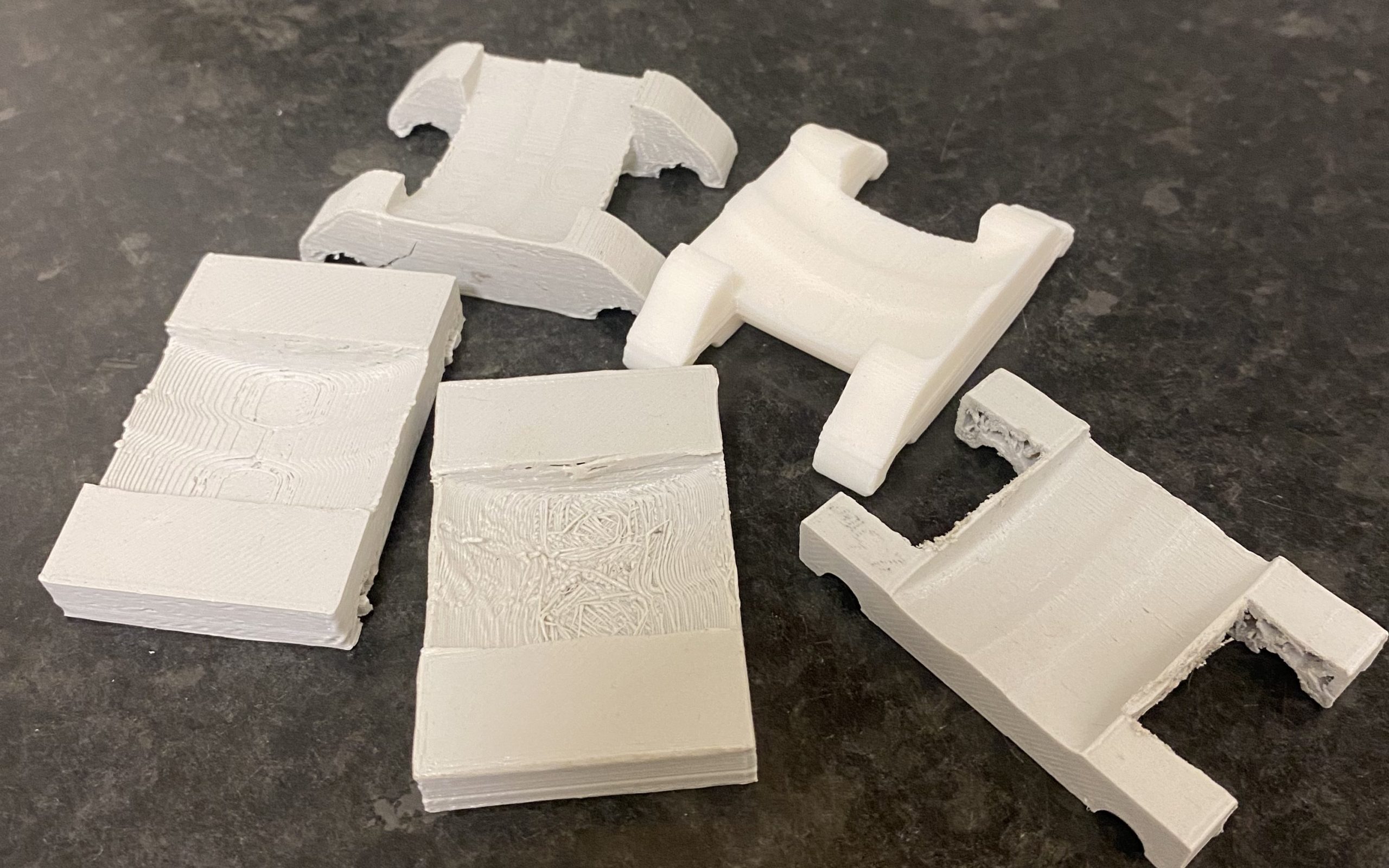
A few more prototypes later
After three or four more prints, some further measuring, and tweaking, I was almost there. Things fitted together, and it was time to see if a real saddle could be mounted using the part I had engineered and printed!!
When a 3D print comes together
I found a couple of suitable bolts in the good old spares box, there it was! Right there, in front of me, was a saddle neatly clamped on top of a carbon seat post that useless moments ago!!
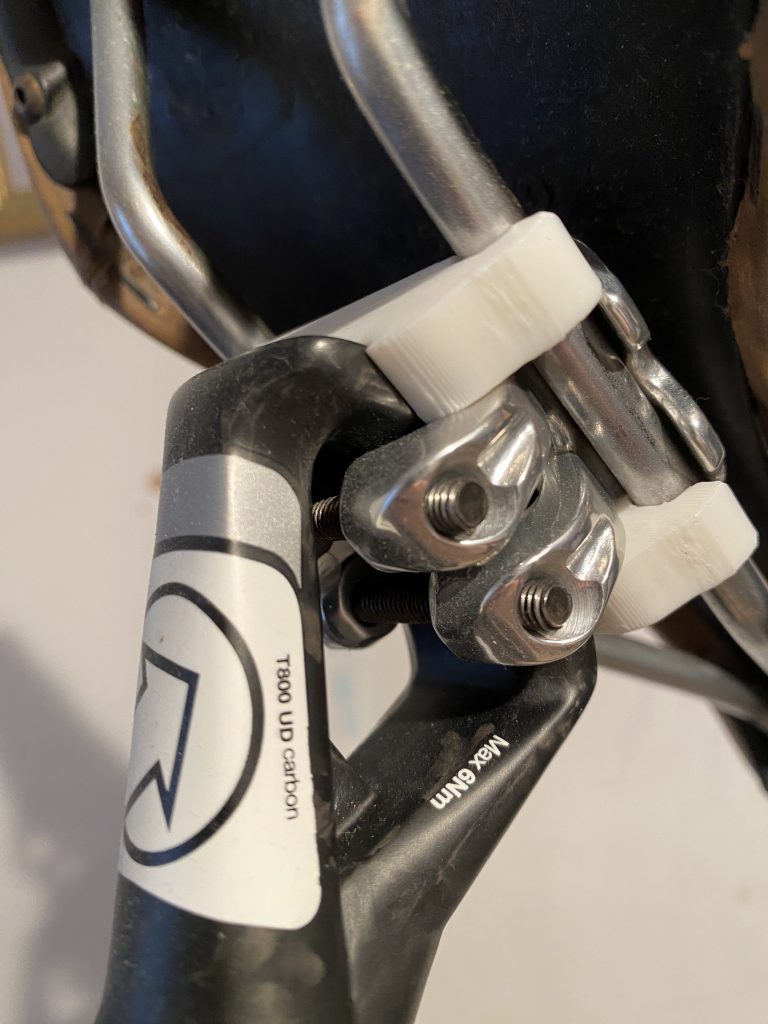
What was fascinating was how well the plastic 3D print worked and how strong it was. I wondered if it would withstand the weight of my blubbery ass on an indoor trainer, so decided to see if I could tighten the clamp enough so that it wouldn’t slip.
There’s a certain satisfaction in seeing something you’ve made being put to use in the way you envisaged.
Sadly, there came a point where it did fail. However, for that particular prototype, I’d set the printer for speed, not quality or strength. Of course, I then printed it full strength to see if it was usable. After all, we already use pedal bodies and other bike parts made of plastic. It was worth a shot.
The solid print was a success; except that it came out slightly warped due to the heat buildup from the mass of hot material as it was laid down by the print head. 3D printers heat the plastic ‘ink’ to well above boiling point; around 230 deg C. However, the warping wasn’t enough to stop me from using the part to mount a saddle. All that’s left is to try it out.
If it doesn’t work, I can move on to printing it from carbon fiber material. Then, if that fails, I can still machine the part from aluminium or Delrin (a machinable plastic used in engineering)…
It’s so satisfying to see something you’ve made put to use in the way you initially envisaged it. There’s also something magical about climbing up a steep learning curve and crossing the finish line with a win.
Leave a Reply